A solar panel wiring diagram is an essential tool for understanding how to connect solar panels to a system, whether it’s a simple off-grid setup or a complex grid-tied system․ These diagrams illustrate the flow of electricity from the solar panels to the load, and they provide details about the components that are necessary to make the system function correctly․ Solar panel wiring diagrams are typically provided in PDF format, which allows users to easily view and print the diagrams․ These diagrams are valuable for anyone who wants to install their own solar panel system, as they provide a clear and concise overview of the wiring process․
Introduction
Solar panel wiring diagrams are essential blueprints for anyone venturing into the world of solar energy․ These diagrams provide a visual representation of how solar panels, charge controllers, batteries, inverters, and loads are interconnected within a solar system․ They are crucial for understanding the flow of electricity from the solar panels to the final destination, whether it’s powering your home, charging your devices, or running appliances․
Understanding a solar panel wiring diagram is key to successfully installing and maintaining a solar system․ It allows you to identify all the components involved, their connections, and the direction of current flow․ This knowledge is vital for troubleshooting any issues that may arise and ensuring the system operates efficiently and safely․
Whether you’re a seasoned DIY enthusiast or a beginner exploring solar options, solar panel wiring diagrams serve as a valuable guide, facilitating informed decision-making and ensuring a smooth and successful solar installation․ They provide a foundation for understanding the intricacies of solar energy, empowering you to harness the sun’s power responsibly and effectively․
Types of Solar Panel Wiring Diagrams
Solar panel wiring diagrams can be categorized based on the configuration of the solar panels themselves․ These configurations determine how the panels are connected in series, parallel, or a combination of both․ The type of wiring diagram you need depends on the specific requirements of your solar system, such as the desired voltage and current output․
Series wiring connects panels one after another, increasing the overall voltage but keeping the current the same․ Parallel wiring connects panels side-by-side, increasing the current while maintaining the voltage․ Combined series-parallel wiring involves both series and parallel connections, allowing for a customized voltage and current output․ Each type of wiring has its own advantages and disadvantages, so careful consideration is necessary to choose the appropriate configuration for your solar system․
Understanding the different types of solar panel wiring diagrams is crucial for selecting the right setup for your specific needs․ It ensures optimal performance, efficiency, and safety for your solar installation․ By carefully evaluating the advantages and disadvantages of each wiring configuration, you can make informed decisions and build a solar system that aligns perfectly with your energy requirements․
Series Wiring
Series wiring is a common configuration in solar panel systems, where multiple solar panels are connected in a chain, one after another․ In this arrangement, the positive terminal of one panel is connected to the negative terminal of the next panel, and so on․ The key characteristic of series wiring is that it increases the overall voltage of the system while maintaining the same current․ This means that if you have two 12-volt solar panels connected in series, the output voltage will be 24 volts, but the current will remain the same․
One advantage of series wiring is that it can be used to achieve higher voltages, which is often necessary for charging batteries or powering appliances․ However, a major disadvantage is that if one panel in a series circuit is shaded or fails, the entire circuit will be disrupted, and the output voltage will drop significantly․ This is because the current cannot flow through the shaded or faulty panel․ Therefore, series wiring is generally not recommended for systems where shading is a concern or where reliability is crucial․
Despite its limitations, series wiring remains a popular choice for some solar panel systems, particularly those with minimal shading and a need for higher voltages․ It offers a simple and efficient way to increase voltage, but it’s important to be aware of its potential drawbacks before implementing this configuration․
Parallel Wiring
Parallel wiring is another common configuration used in solar panel systems, where multiple panels are connected side-by-side․ In this arrangement, all the positive terminals of the panels are connected together, and all the negative terminals are connected together․ Unlike series wiring, parallel wiring increases the overall current of the system while maintaining the same voltage․ If you have two 12-volt solar panels connected in parallel, the output voltage will remain at 12 volts, but the current will double․
A significant advantage of parallel wiring is its greater tolerance to shading or panel failures․ If one panel in a parallel circuit is shaded or fails, the other panels can still operate normally, and the system will continue to produce power, albeit at a slightly reduced output․ This makes parallel wiring a more reliable option for systems where shading is a concern․
However, parallel wiring has its limitations․ One drawback is that it can be more complex to implement, especially if you have a large number of panels․ Additionally, parallel wiring may not be suitable for applications that require high voltages, such as charging batteries with a high voltage rating․ Despite these limitations, parallel wiring offers a reliable and efficient way to increase current in solar panel systems, making it a valuable option for various applications․
Combined Series-Parallel Wiring
Combined series-parallel wiring, also known as a series-parallel configuration, combines the benefits of both series and parallel wiring․ This approach allows for a more flexible system design by adjusting the voltage and current to meet specific requirements․ In a series-parallel configuration, solar panels are first connected in series to increase the voltage, and then these series strings are connected in parallel to increase the current․ This allows for a balance between voltage and current, ensuring a higher power output compared to purely series or parallel wiring․
For example, you could connect two sets of three panels in series, and then connect those two sets in parallel․ This would effectively increase the voltage by a factor of three (using the series connection) and then increase the current by a factor of two (using the parallel connection)․ This approach is particularly advantageous for larger solar panel arrays where the voltage and current requirements need to be carefully managed․
Combined series-parallel wiring offers increased flexibility and power output, making it an ideal choice for more advanced solar panel systems․ However, it requires a more complex understanding of electrical circuits and may require the assistance of a qualified electrician for proper installation․
Components of a Solar Panel System
A solar panel system typically consists of several key components that work together to convert sunlight into usable electricity․ These components are essential for the efficient operation and safety of the system․ Understanding the role of each component is crucial for designing and installing a solar panel system that meets your specific energy needs․
The primary components of a solar panel system include the solar panels themselves, which capture sunlight and convert it into direct current (DC) electricity․ A charge controller regulates the flow of electricity from the solar panels to the battery bank, preventing overcharging and protecting the battery․ The battery bank stores the electricity generated by the solar panels for later use, providing a reliable power source even when the sun isn’t shining․
An inverter converts the DC electricity stored in the battery bank into alternating current (AC) electricity, which is compatible with most household appliances and electronics․ Finally, the load represents the devices and appliances that consume electricity from the system․ These components work together to create a complete solar energy system that can power your home, business, or off-grid applications․
Solar Panel
The solar panel is the heart of any solar energy system, responsible for converting sunlight into electricity․ It’s essentially a collection of photovoltaic cells, typically made of silicon, arranged in a specific configuration to maximize energy capture․ When sunlight strikes these cells, it dislodges electrons, creating an electrical current․ This direct current (DC) electricity is then channeled through wires to the rest of the system․
Solar panels are rated based on their wattage, which indicates the amount of power they can generate under ideal conditions․ The voltage and current output of a solar panel are also important factors to consider when designing a system․ Solar panels come in various sizes and configurations, from small, portable panels suitable for camping to large, stationary panels designed for residential or commercial applications․
Understanding the characteristics of your solar panel is crucial for correctly wiring it into your system․ The wiring diagram will specify the positive and negative terminals of the panel, which must be connected to the corresponding terminals on the charge controller or inverter․ Ensuring proper connections is essential for the safe and efficient operation of your solar panel system․
Charge Controller
The charge controller is a crucial component in a solar panel system, acting as the intermediary between the solar panel and the battery․ Its primary function is to regulate the flow of electricity from the solar panel to the battery, ensuring that the battery is charged safely and efficiently․ Charge controllers protect the battery from overcharging, which can damage it, and prevent excessive current from flowing into the battery, which could cause overheating or even fire․
Charge controllers come in various types, each with its own set of features and capabilities․ Some common types include PWM (Pulse Width Modulation) and MPPT (Maximum Power Point Tracking) controllers․ PWM controllers regulate the current flow by switching the circuit on and off, while MPPT controllers constantly adjust the voltage and current to maximize the power output from the solar panel․ The choice of charge controller will depend on the specific needs of your solar panel system․
The charge controller is typically wired directly to the solar panel, with the positive and negative terminals of the panel connected to the corresponding terminals on the controller․ The charge controller also has terminals for connecting to the battery, ensuring a safe and controlled flow of electricity․ The wiring diagram will clearly indicate the connections for the solar panel, battery, and any other components that may be connected to the charge controller․
Battery
The battery is the heart of an off-grid solar panel system, serving as the storage unit for the energy generated by the solar panels․ When the sun is shining, the solar panels charge the battery, providing a readily available energy source for powering appliances and devices when the sun is not shining․ Batteries come in various types, including lead-acid, lithium-ion, and gel batteries, each with its own advantages and disadvantages in terms of performance, lifespan, and cost․
The battery is typically connected to the charge controller, which regulates the flow of electricity from the solar panel to the battery․ The wiring diagram will indicate the positive and negative terminals of the battery, which must be connected to the corresponding terminals on the charge controller․ The battery capacity, measured in amp-hours (Ah), determines the amount of energy that can be stored․ A larger battery capacity will provide more energy storage, allowing you to power appliances for longer periods without relying on the solar panels․
The battery is an essential component in a solar panel system, providing a reliable source of power when the sun is not available․ The type and size of the battery will depend on the specific needs of your solar panel system, including the size of the load and the duration of time that you need to power your appliances․
Inverter
The inverter plays a crucial role in a solar panel system by converting the direct current (DC) electricity generated by the solar panels into alternating current (AC) electricity, which is compatible with most household appliances and devices․ This conversion is essential for powering standard household appliances like lights, refrigerators, and electronics, which are designed to operate on AC power․
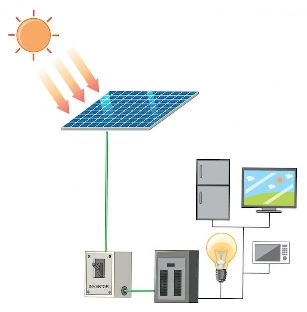
Inverters come in various sizes and types, with the power output and efficiency ratings being important considerations․ The size of the inverter should be selected based on the total power consumption of the appliances that you intend to run․ Inverters can be either grid-tied or off-grid, depending on whether they are connected to the utility grid or operate independently․ A grid-tied inverter allows the system to sell excess energy to the utility grid, while an off-grid inverter provides power only to the appliances connected to the system․
The inverter is typically connected to the battery and the load, allowing the stored energy in the battery to be converted into AC power and distributed to the appliances․ The wiring diagram will clearly show the connections between the inverter, the battery, and the load, ensuring that the system is wired correctly for safe and efficient operation․ Understanding the role of the inverter is essential for setting up a functional and reliable solar panel system․
Load
The “load” in a solar panel system refers to the appliances, devices, or equipment that consume the electricity generated by the solar panels․ These loads can range from simple light bulbs and fans to more complex appliances like refrigerators, televisions, and computers․ The load is the ultimate destination for the electricity produced by the system, and its power requirements determine the overall size and capacity of the solar panel system․
The load is connected to the system through the inverter, which converts the DC electricity from the panels and battery into AC power, suitable for powering standard household appliances․ The wiring diagram will clearly show the connection points between the inverter and the load, ensuring that the electricity flows correctly to the intended devices․ The total power consumption of all the loads connected to the system is a crucial factor in determining the necessary size of the solar panels, battery bank, and inverter․
Understanding the load requirements is essential for designing and installing a solar panel system that can adequately meet the energy needs of your home or business․ The load can be classified into various categories, such as lighting, heating, cooling, and appliances, and each category has specific power requirements that need to be considered during system design and installation․ By properly understanding the load and its connection to the system, you can ensure that your solar panel system operates efficiently and reliably․
Solar Panel Wiring Diagram for a Basic System
A basic solar panel system typically consists of a few key components connected in a straightforward manner․ The diagram for such a system would illustrate the flow of electricity from the solar panels to the battery and then to the load․ The panels are connected in series or parallel, depending on the desired voltage and current output․ The positive terminal of the panels is connected to the positive terminal of the charge controller, while the negative terminal is connected to the negative terminal of the charge controller․
The charge controller regulates the flow of electricity from the solar panels to the battery, preventing overcharging and protecting the battery from damage․ The battery acts as a storage reservoir, providing power to the load when the sun is not shining․ The load, which can be a simple light bulb, a fan, or a small appliance, is connected to the battery through a fuse or circuit breaker for safety․ The diagram will clearly show the positive and negative terminals of each component and the connections between them․
Basic solar panel systems are often used in off-grid applications, where they provide power for homes, cabins, and other locations not connected to the electrical grid․ The wiring diagram for such a system will typically include a simple switch or circuit breaker for disconnecting the load from the system when necessary․ These diagrams are easy to understand and provide a clear visual representation of the system’s components and connections․
